




Search
Related News
- 00
0000-00
How digital transformation improves aerospace fastener traceability - 00
0000-00
GE Aerospace Completes Key Open Fan Low-Pressure Turbine Tests in Poland - 00
0000-00
How creep limits high-temperature materials for advanced propulsion - 00
0000-00
Honeywell Joins Xiamen Aviation Park, Complementing Taikoo Landing Gear Repairs - 00
0000-00
How single-crystal casting expertise builds aerospace process moats
How braking distance shapes high-speed rail signaling system design




How braking distance shapes high-speed rail signaling system design
At 350 km/h, a train can require several kilometers to stop safely, making braking distance a fundamental constraint in signaling design. For teams assessing rail signaling systems for high speed rail, the challenge is not simply calculating stopping distance. It is translating validated braking performance, track gradients, adhesion conditions, and system response times into safe movement authorities and achievable headways.
That translation determines where a train must begin slowing, how much infrastructure remains reserved ahead of it, and whether a proposed timetable is credible. A signaling proposal can have reliable communications and sophisticated positioning yet still disappoint if its capacity claims depend on braking assumptions that the fleet cannot consistently support.
Start with the braking envelope, not a single stopping distance
The familiar relationship, stopping distance = speed squared divided by twice the deceleration, is useful for explaining the scale of the problem. It assumes constant deceleration, level track, and immediate brake application. None of those assumptions is sufficient for a high-speed railway safety assessment.
As an illustrative calculation only, 350 km/h is approximately 97.2 m/s. With an assumed constant deceleration of 0.7 m/s², the braking distance would be about 6.75 km before adding response delays or other allowances. This is not a guaranteed stopping distance for any particular EMU. It shows why modest changes in speed or usable deceleration materially affect infrastructure occupation.
A usable braking model needs a speed-dependent deceleration profile, brake build-up behavior, and defined treatment of uncertainty. It must also distinguish normal service braking from emergency braking. Service braking supports predictable operation and passenger comfort; emergency braking provides the protective intervention assumed by the safety design. Their curves and margins should not be treated as interchangeable.
Several inputs deserve particular scrutiny:
- Guaranteed braking performance across the permitted speed range, loading conditions, and specified equipment failures.
- Brake command transmission and build-up times, including the assumptions used during blended braking transitions.
- Route gradients and the locations where downhill sections extend stopping distance.
- Adhesion assumptions, wheel-slide protection behavior, and any restrictions imposed under degraded conditions.
- Train configuration, brake availability, and the integrity of data supplied to onboard protection.
The relevant question is not “How quickly did the train stop in a demonstration?” It is “What braking performance may the protection system safely credit throughout the defined operating envelope?”
How braking curves become movement-authority limits
A movement authority permits a train to proceed under specified conditions to a defined limit. Automatic train protection supervises its approach to that limit, as well as applicable speed restrictions, using braking curves. These curves convert distance to a target into permissible speeds and intervention thresholds.
The onboard system normally needs to warn or intervene before the train reaches a state from which the credited brake performance can no longer satisfy the target. Driver indications, permitted-speed supervision, and brake intervention therefore occupy different positions in the approach. Exact definitions depend on the protection system and its configured parameters.
Position uncertainty matters here. A train does not know its front position with unlimited precision. Odometry errors, reference updates, and the treatment of location confidence affect how much distance can safely be considered available. The braking calculation must use the appropriate conservative position estimate rather than an unqualified nominal location.
A useful engineering diagram overlays the braking profile, supervision thresholds, route gradient, and location uncertainty against the same target. It exposes assumptions that separate subsystem documents can hide.
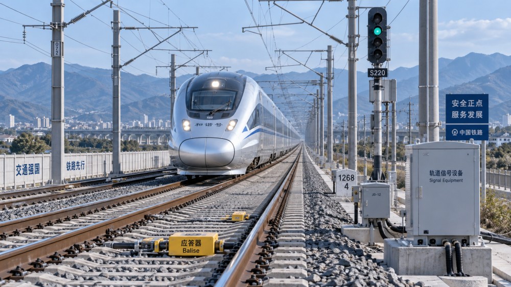
Latency also needs careful allocation. At 350 km/h, one second represents roughly 97 meters of travel. However, adding every radio delay directly to stopping distance is not a sound modeling method. Onboard protection should continue supervising the currently valid authority without requiring a continuous stream of fresh permissions. Communication loss handling, timeout behavior, authority updates, and brake response must be modeled according to the actual architecture, without omissions or double counting.
Block length is not the same as braking distance
In fixed-block operation, train detection divides the railway into discrete sections. Safe separation and braking supervision can extend across several sections; there is no universal rule that every individual block must equal a train’s full stopping distance. The signaling arrangement must provide sufficient authority and warning distance for the applicable speed and braking capability.
Shorter detection sections can allow an authority to advance sooner after a preceding train clears part of the route. That can reduce capacity lost to coarse block boundaries. Yet shortening sections does not eliminate the following train’s braking requirement, and it increases the amount of infrastructure and logic requiring installation, validation, and maintenance.
Moving-block designs reduce dependence on fixed detection boundaries by using train location and other safety-relevant information to determine separation. They still need a justified safe rear position for the preceding train, appropriate uncertainty allowances, and trustworthy train-integrity information wherever separation depends on the reported rear end.
Do not assume that radio-based signaling automatically means moving block. ETCS Level 2, for example, is widely implemented with fixed train-detection sections. Likewise, urban CBTC experience may inform communications and control design, but it does not automatically establish suitability for high-speed mainline operation. Fleet characteristics, interoperability, operating rules, and the applicable approval framework remain decisive.
Claims based on relative braking separation need particular care. Crediting the preceding train’s future motion requires a specific safety justification; it cannot simply be substituted for an absolute stopping-distance requirement to produce a more attractive headway.
Why the same signaling system produces different headways
Braking distance establishes part of the separation envelope, but operational headway also depends on train length, detection and route release, junction conflicts, station dwell, acceleration, and speed differences. A minimum following interval on plain line is not a timetable capacity figure for an entire corridor.
Mixed fleets make the distinction especially important. A following train with weaker guaranteed braking may require earlier supervision even when both trains have the same maximum speed. Conversely, a faster train approaching a slower service can encounter repeated restrictive authorities despite an apparently generous initial interval.
For technical comparison, require simulations to disclose their assumptions rather than presenting only a headline trains-per-hour result. The assessment should include the actual fleet mix, gradients, stopping patterns, junction layout, dwell variability, and relevant degraded modes. It should identify where braking constraints dominate and where infrastructure occupation is the real bottleneck.
There is also a practical trade-off between protection and traffic regulation. An authority extension received after service braking has begun may be safe, but repeated late extensions can create unnecessary slowing and recovery. Capacity evaluation should therefore examine braking interventions and speed profiles, not merely confirm that no safety limit is exceeded.
Standards should connect the model to evidence
A standards list is not a braking safety argument. EN 50126 provides a railway RAMS lifecycle framework, while EN 50129 addresses safety-related electronic signaling systems. Applicable software requirements, national rules, and interoperability obligations must also be identified for the project. The governing editions and acceptance route should be agreed with the relevant authority rather than assumed from a supplier’s previous deployment.
For ETCS projects, the applicable specification baseline and its braking-curve provisions are central. A statement of “ETCS compatibility” does not establish that train data, national values, onboard configuration, and trackside engineering produce the intended supervision behavior together.
Similarly, SIL4 is not a shorthand guarantee of stopping performance. Safety integrity concerns defined safety functions and their implementation. It does not, by itself, prove that a deceleration assumption is valid, a gradient profile is correct, or a claimed headway is achievable.
The evidence chain should connect vehicle brake tests and engineering analyses to the braking model, parameter configuration, route data, integration tests, and safety case. Uncertainties and restrictions must remain visible along that chain. A test result obtained under favorable adhesion cannot quietly become a guaranteed value for a broader operating condition.
Degraded operation reveals whether the design is credible
Regenerative braking illustrates the interface problem. Its availability can depend on traction equipment and the electrical supply’s ability to accept returned energy. If a safety calculation credits it, that credit requires justification for the relevant failure conditions. Otherwise, the guaranteed braking capability must come from the braking resources the safety argument can support.
Low adhesion presents a different challenge. Wheel-slide protection helps manage wheel behavior, but it does not create adhesion that is absent. The operating concept may therefore need restrictions, revised braking assumptions, or other measures under specified conditions. Those measures must be reflected in capacity assessment rather than treated as an issue outside signaling.
Review what happens after loss of communications, unavailable brakes, inconsistent train data, or loss of positioning confidence. Depending on the approved design, the response may involve braking, restricted speed, a different operating mode, or withdrawal from service. Ask how the condition is detected, how the safe response is enforced, and what is required before normal operation resumes.
What to request before accepting a capacity claim
A productive evaluation starts with a matched set of documents: the guaranteed fleet braking envelope, route gradient and speed data, authority and release logic, onboard supervision parameters, and a capacity model using those same assumptions. Configuration ownership matters too. Someone must control changes when vehicles, brake software, route data, or operating restrictions are revised.
Global Aerospace & Advanced Transit Systems (AATS) connects analysis of high-speed EMUs, signaling, safety assurance, and infrastructure maintenance to support technology comparison and lifecycle risk review. For this topic, that cross-system perspective is useful: braking performance cannot be assessed independently of vehicle condition, control interfaces, and the railway’s operating envelope.
Before accepting shorter headways, ask the proposer to demonstrate exactly which assumptions produce them and how those assumptions are maintained in service. If the claimed capacity disappears when validated braking limits, realistic delays, or degraded conditions are introduced, the proposal needs revision—not a more optimistic stopping-distance calculation.
Related News
- Can a rail signaling systems manufacturer support legacy interlocking?Oct 21, 2026Can a rail signaling systems manufacturer support legacy interlocking? Discover how to assess compatibility, safety evidence, and migration plans before choosing a supplier.
- How braking distance shapes high-speed rail signaling system designOct 15, 2026Explore rail signaling systems for high speed rail: learn how braking distance shapes safe separation and realistic headways, and what to check before accepting capacity claims.
- How rail fail safe systems prevent unsafe routes during signal faultsSep 20, 2026Rail fail safe systems prevent unsafe routes during signal faults through restrictive logic, route locking, and proven safety controls. Discover key safeguards.
- How signaling redundancy design for metro systems limits single-point failuresSep 04, 2026Explore signaling redundancy design for metro systems: prevent single-point failures with independent CBTC paths, failover testing, and resilient operations.