








Extreme heat is only part of the challenge facing high temperature advanced propulsion materials: sustained stress can cause creep long before melting becomes a concern.
For technical evaluators, this time-dependent deformation defines critical limits on turbine blade life, dimensional stability, and safe operating conditions across demanding propulsion duty cycles.
Understanding how temperature, load, microstructure, and cooling interact is essential when comparing single-crystal superalloys, refractory alloys, and ceramic matrix composites for specific propulsion components.
The decisive question is whether representative material and component data demonstrate acceptable deformation, rupture margin, and environmental durability throughout the intended service interval under realistic loading.
Why can a component become unusable before its material melts?
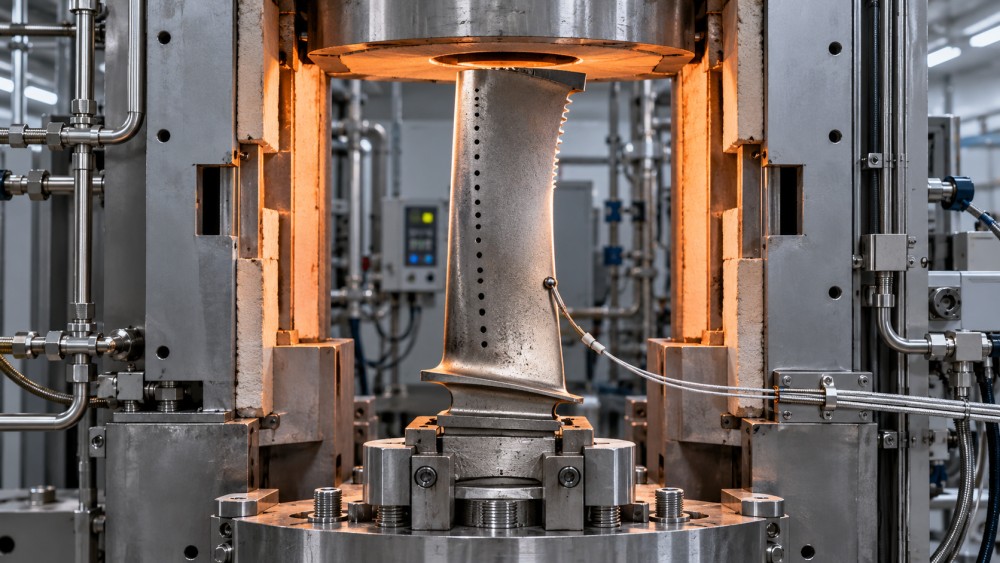
Creep is permanent deformation that develops over time under sustained stress. At elevated temperatures, atomic diffusion and dislocation motion allow deformation below conventional yield limits.
A turbine blade can therefore satisfy a short-duration tensile requirement yet gradually elongate during operation. That elongation can consume tip clearance and increase rubbing risk.
Other consequences include airfoil distortion, changes in cooling passage geometry, and redistribution of local stresses. Functional limits can be exceeded well before complete rupture occurs.
Evaluators should distinguish creep strain limits from rupture life. A material surviving thousands of hours is insufficient evidence if unacceptable distortion develops much earlier in service.
Classical creep curves show primary, secondary, and tertiary stages. The secondary stage often provides a useful rate measure, while tertiary acceleration signals increasing damage or instability.
However, real components experience temperature gradients, changing loads, and local constraints. Their deformation histories may differ substantially from a smooth, constant-load laboratory specimen over time.
Creep becomes relevant at a material-dependent fraction of absolute melting temperature, often around 0.4 to 0.5 for metals. This is guidance, never a design threshold.
For procurement and qualification, the practical requirement is explicit: define permissible deformation, required operating duration, and acceptable failure probability before comparing advertised temperature capabilities between suppliers.
Which temperatures and stresses actually control the assessment?
The relevant temperature is the local material temperature under operating conditions. Combustor exit temperature or turbine inlet temperature cannot directly establish a blade's creep exposure.
Film cooling, internal convection, thermal barrier coatings, and conduction create substantial differences between gas temperature and metal temperature. Those differences also vary across the component.
A credible evaluation therefore needs a temperature distribution, including predicted hot spots and uncertainty. A single average temperature can conceal the region governing component life.
Stress requires similar care. Rotating blades carry centrifugal loads, while aerodynamic forces, attachment constraints, thermal gradients, and local geometry add stresses that vary through operation.
Cooling holes, thin walls, and attachment features produce local concentrations. A nominal section stress may inadequately represent the conditions controlling creep damage or deformation locally.
Many engineering correlations express creep rate as strongly dependent on stress and temperature. Small errors in either input can therefore produce large lifetime prediction errors.
For a meaningful sensitivity study, vary temperature, applied load, wall thickness, and cooling effectiveness within justified tolerances. Report how those variations change predicted life and strain.
For example, evaluate a nominal cooling condition alongside a credible degraded condition. This reveals whether acceptable life depends on cooling performance remaining unusually close to ideal.
How do the main material families compare under sustained load?
No material family wins every propulsion application. Compare candidates at the component level, accounting for load direction, environment, geometry, manufacturing capability, and allowable maintenance intervals.
Nickel-based single-crystal superalloys remain central to demanding turbine airfoils because their engineered microstructures combine high-temperature strength with mature casting, coating, cooling, and inspection practices today.
Removing conventional grain boundaries improves resistance to important grain-boundary creep mechanisms. Nevertheless, crystal orientation, casting defects, secondary phases, and local recrystallization still influence service performance.
Strengthening precipitates can coarsen or change morphology during exposure, affecting deformation resistance. Qualification must consider microstructural stability over the intended duration, including relevant thermal excursions.
Refractory alloys offer attractive high-temperature strength in selected environments. Their practical limits can include oxidation, density, ductility, joining difficulty, and dependence on protective systems during service.
A strong vacuum creep result does not establish suitability for an oxidizing gas path. Environmental protection must survive the same thermal and mechanical history as the substrate.
Ceramic matrix composites, including silicon carbide systems, offer lower density and useful elevated-temperature capability. Their performance depends on fibers, matrix, interfaces, architecture, and environmental protection.
CMC assessment must include matrix cracking, fiber creep, interface changes, and environmental attack. Metallic creep equations and conventional isotropic allowables cannot simply be transferred unchanged.
For technical selection, compare each candidate against the same functional requirement. Include component mass, cooling demand, coating durability, inspectability, and achievable production consistency in that comparison.
What evidence should support a supplier's creep-life claim?
Start with the test conditions behind the headline. Request material temperature, applied stress, environment, specimen geometry, orientation, duration, and the exact criterion used to report life.
A rupture result answers when a specimen failed under specified conditions. A time-to-strain result answers when deformation reached a limit; both may be necessary for qualification.
For metallic materials, ASTM E139 provides a recognized framework for creep and stress-rupture testing. State the applicable edition and any deviations in the qualification documentation.
Verify that specimens represent the offered manufacturing route. Relevant details include composition, heat treatment, casting orientation, section thickness, surface condition, coatings, and permitted repair history.
Ask how many heats, production lots, and specimens support the data. A best-performing specimen does not establish the lower-bound behavior needed for component design decisions.
Request scatter plots and the method used to derive allowable values. Confidence bounds should reflect sample size, batch variation, and the reliability objective of the application.
Short tests can support screening, but long-life extrapolation requires justification. Accelerated conditions may activate different deformation mechanisms or microstructural changes from those expected in service.
Parameters such as Larson–Miller can organize rupture data, but a fitted correlation is not independent validation. Check its calibration range and evidence supporting extrapolation beyond it.
Where available, compare predictions with longer-duration tests excluded from model fitting. Agreement provides stronger evidence than a close fit to the original calibration dataset alone.
How do cooling, coatings, and duty cycles change the answer?
Cooling can reduce creep exposure by lowering material temperature, but it introduces system costs. Compressor bleed air, pressure losses, manufacturing complexity, and maintenance requirements affect overall value.
Additional cooling passages can also reduce load-bearing area and create local stress concentrations. The resulting life benefit depends on the coupled thermal and structural response.
Thermal barrier coatings can reduce substrate temperature when the cooling and heat-transfer conditions support that benefit. Their presence alone does not establish a fixed temperature reduction.
Assess coating aging, bond-coat changes, spallation, and deposit exposure. A local loss of protection can raise substrate temperature and accelerate damage in an already stressed region.
For silicon carbide CMCs, environmental barrier coatings address environmental degradation, including water-vapor-related attack. Their function and failure mechanisms differ from conventional metallic thermal barrier systems.
Duty cycle also changes the governing risk. Long steady operation emphasizes sustained deformation, while repeated starts, shutdowns, and dwell periods introduce interacting creep and fatigue damage.
Thermomechanical fatigue can develop when temperature changes and mechanical constraints produce cyclic strains. Separate creep and fatigue calculations may miss interactions that reduce actual component life.
Qualification should therefore reproduce relevant holds, transients, and environments. For reusable propulsion hardware, inspection intervals and permitted refurbishment must be evaluated alongside the intended operating profile.
How should evaluators connect specimen data to component reliability?
Laboratory data become useful design evidence only when connected to the component's temperature field, stress state, geometry, and manufacturing variability through a validated assessment method.
Uniaxial specimens provide essential information, but actual hardware can experience multiaxial stress and directional material behavior. The constitutive model must represent the relevant response adequately.
For single crystals, orientation-dependent behavior matters near attachments and cooling features. For CMCs, fiber architecture and loading direction can strongly affect deformation and damage development.
Ask whether the analysis predicts only rupture or also displacement, strain redistribution, and clearance change. The latter outcomes often determine whether a component remains usable.
Validation should progress through representative specimens, relevant features, and component testing where appropriate. Each stage should address uncertainties that simpler tests cannot resolve with confidence.
Feature tests can examine thin sections, cooling holes, joints, or coated surfaces. Component tests assess whether the combined thermal, mechanical, and environmental assumptions remain credible.
Inspection evidence should connect predicted damage locations with observable changes. Dimensional measurements, suitable nondestructive methods, and selected metallography can inform decisions about continued service safely.
When uncertainty remains large, additional testing or conservative operating limits may be necessary. The decision should identify which missing evidence most strongly affects the acceptance margin.
What should a practical technical comparison include?
A useful supplier comparison begins with a common operating envelope. Specify local temperatures, load histories, environments, required life, allowable strain, and inspection opportunities before requesting proposals.
Then organize the evidence around decisions that affect qualification and ownership cost. The following questions help expose gaps that headline temperature ratings tend to hide.
- Functional limit: What creep strain, displacement, or clearance change is acceptable, and where must it be measured or predicted?
- Data relevance: Do test specimens represent production material, orientation, coatings, section size, environment, and expected exposure duration?
- Prediction confidence: How are scatter, extrapolation, model uncertainty, and manufacturing variation reflected in the proposed life allowance?
- Protection dependence: What happens to life if cooling effectiveness declines or a coating develops localized damage?
- Service economics: How do inspection, replacement, repair restrictions, cooling demand, and production yield affect lifecycle cost?
Certification and process approvals can support confidence in manufacturing control, but they do not establish component-specific creep capability. Require traceable performance evidence for the proposed configuration.
A lower-cost alloy may require more cooling or shorter replacement intervals. A more capable material may justify its premium only when the system captures those benefits.
For an AATS technical assessment, prioritize evidence linking process capability to service behavior. That connection supports stronger supplier selection, clearer qualification plans, and defensible procurement decisions.
Choose a verified operating envelope, not a headline temperature
Creep limits high temperature advanced propulsion materials through the combined effects of temperature, stress, exposure time, microstructural evolution, and environment. Melting point alone offers little guidance.
The strongest candidate maintains acceptable shape and integrity throughout a defined duty cycle, supported by representative testing, credible predictions, and practical cooling and protection systems.
Technical evaluators should make three requirements explicit: the deformation limit, the evidence supporting life predictions, and the margin available when operating or manufacturing conditions vary.
When those requirements guide material selection, creep becomes a measurable engineering constraint. Buyers can compare suppliers on demonstrated component reliability and the cost of sustaining it.