




Search
Related News
- 00
0000-00
How digital transformation improves aerospace fastener traceability - 00
0000-00
GE Aerospace Completes Key Open Fan Low-Pressure Turbine Tests in Poland - 00
0000-00
How creep limits high-temperature materials for advanced propulsion - 00
0000-00
Honeywell Joins Xiamen Aviation Park, Complementing Taikoo Landing Gear Repairs - 00
0000-00
How single-crystal casting expertise builds aerospace process moats
How thermal gradients affect defects in single-crystal casting




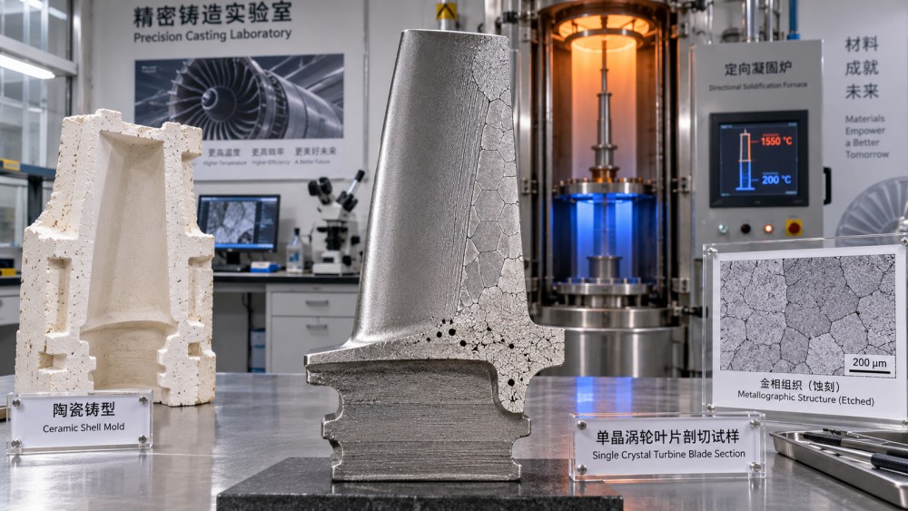
A single-crystal turbine blade can pass through a qualified casting cycle yet develop stray grains near a platform, freckle chains along a thick section, or porosity beneath a section transition. These defects may appear together, but they do not have the same cause. Thermal gradients influence each by controlling the direction of solidification, the shape and depth of the mushy zone, and the availability of liquid metal for feeding.
The central judgment is that a strong, appropriately directed local thermal gradient generally supports controlled single-crystal growth, but increasing the nominal furnace gradient alone does not guarantee fewer defects. Local heat flow, interface velocity, alloy chemistry, and blade geometry determine the outcome. Evaluating single-crystal casting process defects therefore requires evidence from the vulnerable regions of the casting—not just furnace settings or an overall yield figure.
The gradient that matters is at the moving solidification front
In directional solidification, heat is extracted predominantly toward the already solidified portion of the casting. A seed or grain selector establishes the crystal that should continue through the component. As the mold moves through the furnace thermal field, dendrites advance into the liquid while interdendritic liquid solidifies behind their tips.
The thermal gradient, commonly represented by G, describes how rapidly temperature changes with position. The relevant quantity is the local gradient near the solidification front, including its direction. A furnace setpoint difference is not a direct measurement of this gradient: mold insulation, radiation, ceramic cores, neighboring castings, and section thickness all modify the temperature field.
Solidification velocity, V, describes the speed of the advancing interface. Withdrawal speed influences it, but the two need not match locally during transitions or changes in front curvature. The ratio G/V helps describe susceptibility to constitutional undercooling, while the product G × V relates to cooling rate under suitable local assumptions. Neither is a universal acceptance criterion for a complex blade.
Constitutional undercooling occurs when solute redistribution changes the local liquidus temperature such that liquid ahead of the advancing front becomes undercooled relative to its composition. A low stabilizing gradient relative to growth velocity can increase this tendency. Single-crystal superalloys normally grow dendritically, however, so the objective is not to create a perfectly planar interface. It is to maintain controlled dendritic growth without allowing competing grains or damaging flow instabilities.
Geometry can defeat an acceptable furnace setting
A thin airfoil and a thick platform do not release heat at the same rate. When the selected crystal reaches a sudden lateral expansion, existing dendrites must grow sideways into metal that may already be undercooled. The platform extremity can then nucleate independently before the intended crystal arrives.
Cooling passages complicate the pattern further. Ceramic cores change heat-transfer paths and restrict the available metal section. A region beside a core may solidify differently from an apparently similar region near the outer mold wall. Cluster position and radiative shadowing can also produce lateral temperature differences between castings processed in the same furnace run.
These conditions bend the solidification front. The nominal withdrawal direction may remain vertical while local dendrites encounter inclined interfaces, isolated liquid pockets, or regions where the gradient weakens. A useful thermal model must therefore resolve critical transitions rather than report only a centerline temperature history.
Different defects reveal different thermal failures
Stray grains: the selected crystal loses the race
Stray grains form when another crystal nucleates and grows in material intended to inherit the selected orientation. Platform corners, shrouds, abrupt section enlargements, and locally undercooled surfaces are important locations to examine. A weakened or poorly directed gradient can allow undercooling to develop beyond the reach of the existing dendrite network.
The diagnostic question is whether the defect starts at a geometrical transition, at a mold surface, or near the selector. A transition-related grain suggests a mismatch between local cooling and lateral growth. A grain originating near the selector may instead indicate selection problems or an interruption in growth continuity. Surface reactions or nucleating inclusions can contribute, so a thermal explanation should not automatically exclude material-related causes.
Orientation mapping across the affected region helps distinguish a genuinely separate grain from gradual orientation variation or a low-angle boundary. That distinction matters because the corrective action and allowable condition may differ under the applicable component specification.
Freckles: convection destabilizes the mushy zone
Freckles are associated with solute-rich liquid flowing through the partially solidified dendritic network. Composition changes during freezing can create density differences that drive buoyancy-related convection. Under susceptible conditions, this flow develops channels and produces chemically segregated regions, often containing chains of misoriented grains.
A lower gradient can deepen the mushy zone and create a larger region in which this instability develops. Dendrite spacing, permeability, alloy-dependent density changes, component size, and front inclination also influence the risk. Freckling is therefore not adequately explained as “cooling too slowly,” nor should it be treated simply as another form of surface grain nucleation.
Assessment methods based on mushy-zone convection or Rayleigh-type criteria require alloy properties and geometric assumptions. Their thresholds are model-dependent. For supplier evaluation, ask whether the prediction has been correlated with actual freckle locations for the relevant alloy and casting configuration, rather than accepting a generic numerical threshold.
Shrinkage porosity: feeding paths close too early
Solidification shrinkage requires liquid metal to feed the contracting structure. Thermal gradients determine the sequence in which regions freeze and whether the remaining liquid stays connected to a feeding source. An isolated last-to-freeze pocket can retain insufficient liquid and develop shrinkage cavities or interdendritic microporosity.
A steeper gradient can shorten the mushy zone, but it does not automatically remove porosity. Feeding also depends on dendritic permeability, pressure conditions, section connectivity, and the local solidification sequence. Thermal changes that help suppress stray grains may relocate the last-to-freeze region or close a narrow feeding path earlier.
Porosity should also be separated from gas-related defects. Location and morphology provide clues, but metallography, process records, and suitable volumetric inspection may be needed to establish the mechanism. Treating every void as evidence of an inadequate gradient can lead to the wrong process adjustment.
Higher gradients introduce trade-offs, not a universal cure
Increasing heat extraction can improve directional growth and reduce the extent of the mushy zone. Depending on the equipment, this may involve changes to the hot-zone arrangement, baffle, cooling conditions, or withdrawal profile. The process change must be judged at the casting level: a sharper furnace transition does not prove that every critical blade region experiences a more favorable gradient.
Excessive thermal nonuniformity can also increase mechanical stresses as the casting and ceramic constrain one another during cooling. Local plastic deformation may later contribute to recrystallization during heat treatment. This is a different mechanism from a stray grain formed during solidification, and it requires examination of both the casting history and subsequent processing.
Withdrawal adjustments create another trade-off. Slower movement may help existing dendrites occupy a section expansion before independent nucleation occurs, yet it can change mushy-zone residence time and convective behavior. Faster movement changes interface conditions and feeding. The correct direction of adjustment depends on the identified defect mechanism, not on a general rule that slower or faster is always better.
A practical sequence for investigating a rejected blade
- Locate and classify the defect first. Record its position relative to the selector, platform, core, and section transitions. Separate grain defects, segregation, and porosity before choosing a thermal correction.
- Establish when it formed. Compare as-cast and post-heat-treatment evidence where available. A grain visible after solution treatment may represent recrystallization rather than new nucleation during casting.
- Reconstruct the local thermal conditions. Review withdrawal history, furnace stability, mold preheat, cooling configuration, and cluster position. Examine gradient direction and interface curvature at the defect location.
- Challenge the model assumptions. Check how radiation, contact conditions, temperature-dependent material properties, and core geometry were represented. Thermocouple measurements used for validation should have documented locations and measurement limitations.
- Test a mechanism-specific change. Use a controlled trial with traceable configuration changes and inspection focused on the predicted risk regions. Avoid changing several interacting variables without a plan to separate their effects.
A credible corrective trial must look for displaced defects as well as reduced defects. Eliminating a platform grain is not sufficient if the revised thermal field creates porosity deeper in the blade or increases post-treatment recrystallization.
Evidence needed to assess supplier capability
Request a process window linked to the actual alloy, component geometry, mold system, and casting configuration. It should identify controlled variables, permitted variation, and the basis for those limits. A temperature range without corresponding withdrawal conditions and geometry is weak evidence of single-crystal casting control.
Inspection records should connect indications to individual castings and furnace runs. Grain assessment and orientation measurements address crystallographic continuity; radiography or computed tomography address volumetric indications within their demonstrated detection capability. Penetrant inspection can reveal surface-breaking defects but cannot establish internal crystal orientation. Sectioning and metallography remain valuable for process qualification and unresolved mechanisms.
Model validation should demonstrate agreement with relevant measurements and observed defect locations. Matching one temperature trace does not necessarily validate predictions of interface shape, mushy-zone flow, or porosity. Ask which outputs were validated and what uncertainty remains near the geometry most prone to rejection.
For acceptance, use the applicable drawing, material specification, customer requirements, and approved inspection procedures. Limits for orientation deviation, boundaries, freckles, and porosity are component-specific; no single thermal-gradient value certifies a blade as acceptable. Quality-system or special-process accreditation can support confidence in control, but it does not replace part-specific qualification or acceptance evidence.
The strongest capability claim is a demonstrated link between local thermal conditions, correctly classified defects, and repeatable inspection results across the qualified operating window. When that link is missing, a successful furnace recipe remains less convincing than a process whose limitations are measured and understood.
Related News
- GE Aerospace Completes Key Open Fan Low-Pressure Turbine Tests in PolandOct 28, 2026GE Aerospace completes Open Fan low-pressure turbine tests in Poland. Explore what this milestone means for future engine efficiency, suppliers and aircraft procurement.
- How creep limits high-temperature materials for advanced propulsionOct 27, 2026High temperature advanced propulsion materials face creep limits. Explore alloy options, cooling strategies, and test evidence to make smarter, more reliable material selections.
- How single-crystal casting expertise builds aerospace process moatsOct 26, 2026Discover how aerospace process moats emerge from single-crystal casting expertise, consistent yields, and qualification—and what makes turbine blade suppliers hard to replace.
- GE Aerospace Accelerates T901 Turboshaft Development for US ArmyOct 24, 2026GE Aerospace accelerates T901 turboshaft development for the US Army’s ITEP. Explore the 3,000-shp engine’s efficiency goals and potential role in the UH-60 Black Hawk.