




Search
Related News
- 00
0000-00
How digital transformation improves aerospace fastener traceability - 00
0000-00
GE Aerospace Completes Key Open Fan Low-Pressure Turbine Tests in Poland - 00
0000-00
How creep limits high-temperature materials for advanced propulsion - 00
0000-00
Honeywell Joins Xiamen Aviation Park, Complementing Taikoo Landing Gear Repairs - 00
0000-00
How single-crystal casting expertise builds aerospace process moats
How aerospace propulsion technology systems affect engine efficiency




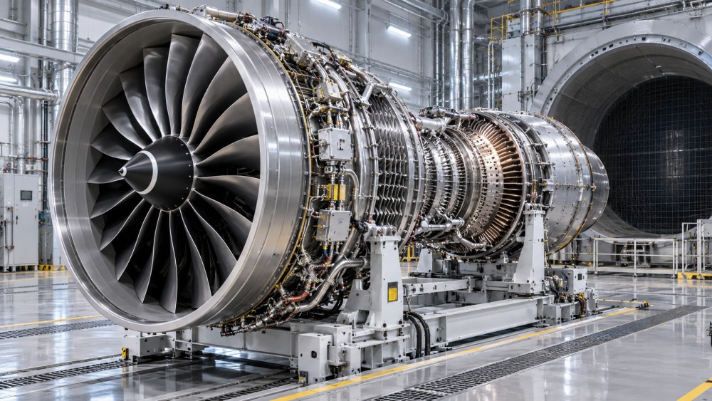
Engine efficiency is not determined by a single breakthrough in fan design, turbine temperature, or fuel control. It is the result of a tightly coupled propulsion system in which aerodynamics, thermodynamics, materials, cooling, combustion, mechanical architecture, and control logic must perform together across the mission profile. A design that improves one parameter in isolation can reduce net efficiency if it adds excessive weight, demands too much cooling air, narrows operating margin, or increases maintenance burden.
The practical measure is therefore not simply maximum thrust or peak thermal efficiency. It is the fuel required to produce useful propulsive work, while retaining adequate stall margin, temperature margin, emissions compliance, dispatch reliability, and certified containment capability. For a civil turbofan, this is commonly assessed through specific fuel consumption (SFC) over representative flight conditions rather than at a single static test point. For military, business aviation, rotorcraft, and space applications, the relevant balance changes, but the same systems logic applies.
Efficiency begins with the conversion of fuel energy into useful thrust
A gas-turbine engine loses energy in several places: the exhaust may leave with unused kinetic energy, compressor and turbine components create aerodynamic losses, combustion is not perfectly uniform, heat is rejected through cooling flows, and accessories consume shaft power. Aerospace propulsion technology systems affect efficiency by reducing these losses without making the engine too heavy, complex, or difficult to maintain.
Two concepts need to be separated. Thermal efficiency describes how effectively the engine converts fuel chemical energy into shaft work or jet power. It generally benefits from a higher effective overall pressure ratio and a higher turbine inlet temperature, within material and cooling limits. Propulsive efficiency describes how effectively that power becomes aircraft thrust. It improves when the engine accelerates a larger mass of air by a smaller velocity increase, rather than a smaller mass by a very high velocity increase.
This distinction explains the architecture of modern high-bypass turbofans. Their large fan moves substantial airflow around the core, producing thrust with a lower exhaust velocity than a pure turbojet. The core remains responsible for generating the power that drives the fan, so its compressor efficiency, combustor performance, turbine temperature capability, and cooling system still have a direct effect on total fuel burn.
There is no universal “best” bypass ratio or pressure ratio. An ultra-high-bypass concept may be attractive for subsonic transport aircraft, yet fan diameter, nacelle drag, ground clearance, blade-off containment, noise, gearbox capability, and installation geometry can limit its value. At higher flight Mach numbers, the inlet and nacelle penalties become more significant. A propulsion assessment must therefore evaluate the complete installed engine-airframe system, not only the uninstalled engine cycle.
Compressor and turbine aerodynamics set the internal loss budget
Every compressor and turbine stage introduces losses through boundary layers, secondary flows, tip leakage, shock formation in transonic sections, surface roughness, and flow separation. Small aerodynamic improvements can be meaningful because they compound across multiple stages and persist over a long operating life.
Compressor design is especially important because the compressor consumes a major share of turbine work. Higher compressor efficiency reduces the turbine power needed to achieve a given pressure ratio. However, an aggressive compressor operating line can leave inadequate surge margin during rapid acceleration, inlet distortion, icing conditions, bleed extraction, or deterioration. The most efficient design-point compressor is not necessarily the most efficient engine in service if its operability margin requires conservative control scheduling or frequent maintenance intervention.
Variable inlet guide vanes and variable stator vanes are examples of propulsion system components that improve the usable efficiency range rather than merely the peak value. By adjusting incidence angles as spool speed and airflow change, they help the compressor remain away from stall while reducing off-design losses. Their benefit depends on actuator precision, response time, wear resistance, and control-law calibration. A variable geometry system that drifts mechanically or suffers position-sensing errors can undermine both performance and operability.
Turbine efficiency is similarly linked to blade profile design, sealing, leakage control, and cooling. The high-pressure turbine extracts energy from the hottest gas stream to drive the high-pressure compressor; downstream turbine stages power the fan or low-pressure compressor. Improvements in turbine efficiency can be converted into lower fuel flow, higher available thrust, additional cooling margin, or a different cycle balance. Which outcome is selected depends on the engine’s design requirements.
Higher turbine temperature is valuable only when cooling and materials support it
Raising turbine inlet temperature is one of the most powerful ways to increase gas-turbine thermal efficiency and specific power. It is also one of the most misunderstood indicators in engine comparison. A higher nominal temperature does not automatically mean a more efficient propulsion system, because the hot-section hardware must survive thermal gradients, oxidation, corrosion, low-cycle fatigue, creep, vibration, and centrifugal loading.
Single-crystal nickel-based superalloys, directionally solidified alloys, thermal barrier coatings, and advanced casting processes allow turbine airfoils to operate in environments beyond the bulk alloy’s uncooled temperature capability. Yet these materials are not independent solutions. Their performance relies on controlled chemistry, grain structure where applicable, coating adherence, internal passage integrity, heat-treatment consistency, and non-destructive inspection.
Film cooling illustrates the central trade-off. Compressor discharge air is routed through internal blade passages and discharged through carefully placed holes to create a protective cooler layer on the external airfoil surface. This protects the metal, but the cooling air was compressed using engine work and is no longer available for the primary gas path in the same way. Excessive cooling bleed can reduce cycle efficiency; insufficient or poorly distributed cooling reduces life and increases risk of distress.
The relevant engineering question is not whether an engine uses film cooling, but how effectively its cooling architecture controls metal temperature with the minimum necessary bleed flow. This requires attention to hole geometry, internal heat-transfer features, coating condition, local gas-path temperature distribution, blockage tolerance, and manufacturing variation. Cooling holes can be affected by deposition, erosion, or contamination. A design with excellent nominal cooling performance may still create lifecycle exposure if inspection access and repair capability are limited.
Ceramic matrix composites (CMCs) can reduce cooling demand in selected hot-section applications because they retain useful properties at higher temperatures and lower density than metallic alternatives. Their deployment, however, requires evaluation of environmental barrier coatings, joining methods, impact sensitivity, oxidation behavior, repair procedures, and the maturity of the qualified supply chain. Material substitution should be assessed as a change to the thermal-management system, not as a stand-alone weight-saving measure.
Combustion efficiency must coexist with emissions and operability
The combustor has to release fuel energy efficiently and evenly while avoiding lean blowout, autoignition, flashback in relevant architectures, unacceptable pressure loss, combustion instability, and excessive pollutant formation. Its influence reaches far beyond fuel burn. Poor outlet temperature uniformity creates local turbine overheating, forcing more conservative cooling design or shortening component life.
Lean-burn and staged combustion approaches seek to control flame temperature and reduce nitrogen oxides (NOx), particularly during high-power operation. The engineering challenge is that lower-emission combustion can narrow stability margins or increase susceptibility to pressure oscillations. Fuel injector design, atomization, swirl, dilution airflow, combustor liner cooling, fuel properties, and control scheduling all affect the result.
A useful assessment separates combustion efficiency from engine-level efficiency. Near-complete fuel oxidation is desirable, but a combustor cannot be judged by that metric alone. Pressure loss across the combustor reduces cycle performance; poor pattern factor raises turbine cooling demand; unstable operation may impose limits on fuel scheduling. The better solution is the one that achieves required emissions and operability while preserving the downstream turbine’s temperature margin.
For civil aircraft engines, emissions certification is associated with the International Civil Aviation Organization framework in Annex 16, Volume II, including standards developed through the Committee on Aviation Environmental Protection (CAEP). Certification limits should not be treated as a generic proof of fuel efficiency. They address defined emissions requirements under prescribed test conditions. A technically sound comparison considers the certified emissions basis alongside mission fuel burn, deterioration behavior, and installation effects.
Controls turn component capability into usable engine efficiency
Full Authority Digital Engine Control (FADEC) systems continuously coordinate fuel flow, variable stator positions, bleed valves, clearance-control functions, active tip-clearance systems where fitted, and engine protection limits. Their importance grows as engines use higher pressure ratios, tighter thermal margins, more variable geometry, and more integrated aircraft systems.
A control system can improve fuel efficiency by keeping the engine closer to its optimum operating line as altitude, ambient temperature, aircraft speed, throttle demand, and component condition change. It can also prevent conditions that would damage efficiency or hardware: compressor surge, turbine overtemperature, overspeed, inadequate acceleration margin, or unacceptable rotor imbalance.
Control quality must be assessed as both a software and a system-integration issue. Sensor bias, response lag, wiring faults, actuator hysteresis, data-validation logic, and degraded-mode behavior affect real engine operation. The control architecture must also meet the applicable certification basis for the engine and aircraft installation. For software assurance, DO-178C is widely used in airborne systems, while its applicability and assurance level depend on the specific function and certification context. It should not be assumed that compliance with a software standard alone demonstrates engine performance or safety compliance.
Health monitoring adds another efficiency dimension. Trending exhaust gas temperature margin, vibration, oil debris, fuel flow, spool speed, and other validated parameters can reveal deterioration before it becomes a dispatch disruption or an avoidable fuel penalty. The value of such data depends on measurement quality and engineering interpretation. A trend may indicate compressor fouling, turbine clearance growth, sensor error, bleed leakage, or an operating-environment effect; it is not automatically evidence of a single component defect.
Mechanical architecture changes the optimum cycle
Geared turbofans demonstrate how a mechanical subsystem can reshape the whole propulsion efficiency balance. A reduction gearbox allows the fan and low-pressure spool to rotate closer to their respective efficient speeds. This can support a larger, slower fan while allowing the low-pressure turbine to run faster. The gain is not “free”: gearbox mass, lubrication, bearing loads, gear thermal management, torsional dynamics, reliability targets, and containment considerations become part of the engine’s efficiency case.
Open-fan and other unducted architectures pursue high propulsive efficiency through very large effective airflow and lower jet velocity. Their evaluation requires particular attention to installation aerodynamics, aeroacoustics, blade containment philosophy, structural dynamics, aircraft integration, and certification pathways. A favorable cycle analysis cannot substitute for assessment of these system constraints.
For propulsion systems with electric machines, hybridization, or distributed propulsors, efficiency must be measured across the entire energy chain. Generator losses, power electronics, thermal rejection, cable mass, battery or energy-storage limitations, and fault-management architecture may outweigh a local propulsor benefit. Comparing only motor efficiency or propeller efficiency does not answer whether the aircraft-level propulsion system is more efficient.
Clearance control and deterioration can matter as much as nominal design efficiency
Tip clearance between rotating blade tips and stationary casings has a strong influence on compressor and turbine leakage. During different operating conditions, rotors and casings expand at different rates. Active clearance-control systems manage casing temperature or geometry to maintain a smaller safe clearance over the flight cycle. Reduced leakage improves aerodynamic efficiency, but the system must avoid rub events, uneven thermal distortion, control malfunction, and unnecessary bleed-air use.
New-engine performance can be misleading when decisions depend on multi-year operating economics. Compressor fouling, erosion, seal wear, coating degradation, cooling-passage blockage, nozzle-area changes, and clearance growth can all shift SFC and exhaust gas temperature margin. The rate and consequence of deterioration depend on operating environment, maintenance practices, mission severity, and component design.
This makes maintainability part of propulsion efficiency. Wash procedures, borescope access, module replacement strategy, repair limits, coating restoration capability, and availability of approved repair data determine whether the engine can return to its intended condition. An architecture that promises a small design-point fuel advantage but requires frequent intrusive maintenance may not produce the lower lifecycle fuel-and-maintenance burden expected in service.
What a technically credible comparison should examine
When comparing aerospace propulsion technology systems, headline thrust and advertised fuel-burn improvement are insufficient. The assessment should establish the reference mission, including altitude, Mach number, ambient conditions, payload assumptions, reserve requirements, and expected duty cycle. A regional aircraft, long-range transport, supersonic platform, rotorcraft, and unmanned system do not place the same value on bypass ratio, transient response, thermal margin, or maintenance interval.
The most informative technical evidence connects component-level claims to engine-level consequences:
- Compressor maps and surge-margin management across the relevant operating envelope;
- Combustor pressure loss, pattern factor, emissions behavior, and stability margin;
- Turbine material capability, cooling-flow demand, coating system, and life-management assumptions;
- Fan, gearbox, nacelle, and inlet effects on installed propulsive efficiency;
- Control-system fault handling, sensor redundancy, and degraded operating modes;
- Deterioration sensitivity, inspection intervals, repair constraints, and retained performance after maintenance;
- Evidence that the proposed configuration can meet the applicable engine certification requirements, including the requirements of FAA 14 CFR Part 33 or EASA CS-E where those frameworks apply.
Efficiency in aerospace propulsion is therefore best understood as managed margin. The engine must convert energy efficiently while retaining enough aerodynamic, thermal, mechanical, and control margin to remain safe and serviceable through real operating conditions. The strongest propulsion designs are not those that maximize one theoretical cycle parameter, but those that preserve an efficient system balance from first flight through repeated maintenance cycles.
Related News
- GE Aerospace Completes Key Open Fan Low-Pressure Turbine Tests in PolandOct 28, 2026GE Aerospace completes Open Fan low-pressure turbine tests in Poland. Explore what this milestone means for future engine efficiency, suppliers and aircraft procurement.
- How creep limits high-temperature materials for advanced propulsionOct 27, 2026High temperature advanced propulsion materials face creep limits. Explore alloy options, cooling strategies, and test evidence to make smarter, more reliable material selections.
- How single-crystal casting expertise builds aerospace process moatsOct 26, 2026Discover how aerospace process moats emerge from single-crystal casting expertise, consistent yields, and qualification—and what makes turbine blade suppliers hard to replace.
- GE Aerospace Accelerates T901 Turboshaft Development for US ArmyOct 24, 2026GE Aerospace accelerates T901 turboshaft development for the US Army’s ITEP. Explore the 3,000-shp engine’s efficiency goals and potential role in the UH-60 Black Hawk.