




Search
Related News
- 00
0000-00
How digital transformation improves aerospace fastener traceability - 00
0000-00
GE Aerospace Completes Key Open Fan Low-Pressure Turbine Tests in Poland - 00
0000-00
How creep limits high-temperature materials for advanced propulsion - 00
0000-00
Honeywell Joins Xiamen Aviation Park, Complementing Taikoo Landing Gear Repairs - 00
0000-00
How single-crystal casting expertise builds aerospace process moats
Why single-crystal alloys resist creep at high temperatures




Why single-crystal alloys resist creep at high temperatures
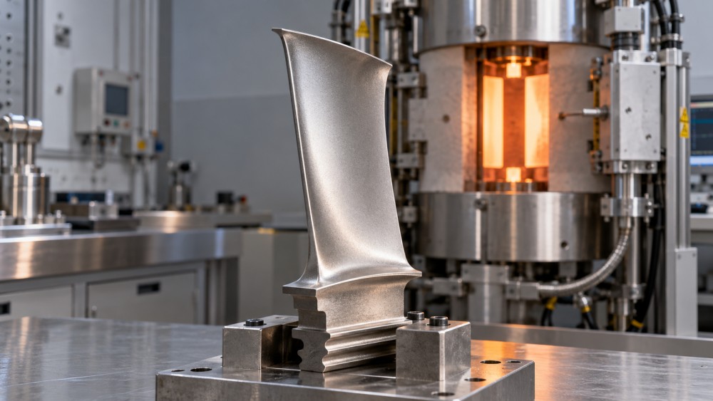
Why can a single-crystal turbine blade withstand prolonged heat and centrifugal loading better than a conventional cast alloy? For engineers evaluating high temperature creep resistant alloys, the answer lies in eliminating grain boundaries and controlling the nickel-based superalloy’s strengthening microstructure. These features suppress key deformation mechanisms, but performance still depends on crystal orientation, temperature, stress, and manufacturing quality.
The practical question is not whether a material is called “single crystal.” It is whether the finished component retains the required creep resistance under its actual thermal and mechanical loading. That distinction matters when comparing alloy grades, qualifying a casting supplier, or assessing turbine blade life.
Creep is a time-dependent problem, not simply a strength limit
Creep is progressive deformation under sustained stress at elevated temperature. A turbine blade can therefore accumulate permanent strain even when its applied stress remains below the short-term yield strength measured at that temperature. Centrifugal loading stretches the blade, while uneven heating and cooling create additional local stresses.
For a rotating airfoil, excessive creep can change tip clearance, distort cooling passages, and redistribute loads before rupture occurs. Consequently, time to a specified creep strain may be more relevant to a design decision than rupture life alone.
Temperature and stress strongly affect the rate of deformation. A material comparison without both conditions is incomplete. So is a comparison that ignores exposure time: a short tensile test cannot establish long-term creep capability.
Removing grain boundaries closes important damage paths
A conventional equiaxed casting contains many grains with different crystallographic orientations. Their boundaries can support sliding, provide relatively fast diffusion paths, and become sites for cavity formation under suitable high-temperature loading conditions. Boundaries transverse to the principal tensile load are particularly undesirable in creep-critical turbine airfoils.
Directionally solidified alloys improve this arrangement by producing columnar grains broadly aligned with the blade axis. They reduce transverse boundaries, but boundaries remain between adjacent columns. Single-crystal casting goes further: the intended component is one continuous crystal, without the high-angle grain-boundary network of a polycrystalline casting.
This removes grain-boundary sliding and grain-boundary cavitation as bulk deformation and damage routes in a sound single crystal. It also gives alloy designers greater freedom to adjust elements traditionally used for grain-boundary strengthening, potentially improving heat-treatment flexibility.
It does not remove creep itself. Dislocations still move within the crystal, atoms still diffuse, and casting pores can still initiate damage. Single-crystal alloys address a major weakness of conventional castings; they do not create a defect-free or indefinitely stable material.
The gamma–gamma-prime structure supplies the other half of the resistance
Commercial single-crystal turbine alloys are generally nickel-based superalloys built around two principal phases: a gamma matrix and gamma-prime strengthening precipitates. Gamma is a nickel-rich solid solution. Gamma prime is an ordered phase commonly described as Ni3(Al,Ta,Ti), although its composition varies with alloy design.
The precipitates are not simply hard particles scattered through soft metal. Their ordered structure and close crystallographic relationship with the matrix create obstacles to dislocation movement. Depending on temperature, stress, and microstructure, dislocations must shear the precipitates or move through the matrix channels and around them through thermally activated processes.
Precipitate size, spacing, shape, and volume fraction all influence this resistance. Solution treatment and aging establish the starting microstructure, while service exposure changes it. Two castings with the same nominal chemistry can therefore show different creep behavior if their heat treatments, segregation levels, or resulting microstructures differ.
Refractory alloying elements, including tungsten, molybdenum, and rhenium in selected grades, contribute to high-temperature strength through effects on solid-solution strengthening and diffusion. Adding more is not automatically beneficial. Density, segregation, castability, cost, and the risk of undesirable phase formation constrain the composition.
Under prolonged high-temperature stress, gamma-prime precipitates may undergo directional coarsening, commonly called rafting. Its effect depends on lattice misfit, loading direction, and exposure conditions. Certain raft structures can impede deformation; continued evolution can also accompany degradation. Rafting should not be classified as universally beneficial or universally harmful.
Crystal orientation changes the result
A single crystal is anisotropic: its elastic and deformation properties depend on direction. Turbine blades are commonly cast with a <001> crystallographic direction close to the blade’s longitudinal axis. This orientation offers a useful combination of creep performance and relatively low elastic modulus along the principal loading direction, which can help manage thermally induced stresses.
However, “<001>-oriented” is not a complete acceptance requirement. The permitted angular deviation must come from the applicable drawing or material specification. Secondary orientation can also matter where bending, cooling-hole geometry, or multiaxial stress makes the loading more complex than simple axial tension.
Orientation is typically assessed using X-ray diffraction methods. Qualification should connect the measured orientation to the actual component and test specimen, rather than assuming every part from a casting batch has an equivalent crystallographic alignment.
Where the advantage stops
Single-crystal construction does not make a turbine blade independent of its cooling system. The relevant material input is local metal temperature, not combustion-gas temperature. Internal cooling, film cooling, and thermal barrier coatings help maintain that difference. A blocked passage or degraded coating can move a local region outside the conditions used to substantiate its life.
Microstructural stability also imposes limits. Gamma-prime coarsening, oxidation, hot corrosion, and the formation of topologically close-packed phases can reduce capability, depending on alloy and exposure. These phases can deplete strengthening elements from the matrix and may provide crack-initiation sites.
Manufacturing defects deserve equal attention. Stray grains, unacceptable low-angle boundaries, porosity, and recrystallized surface regions can undermine the intended single-crystal structure. Recrystallization is a particular concern when local plastic deformation is followed by high-temperature processing. Repair and refurbishment routes therefore need their own technical justification.
For components dominated by weldability, moderate-temperature fatigue, or fabrication cost, a wrought or conventionally cast alloy may be more appropriate. The single-crystal route earns its complexity where sustained high-temperature loading makes its directional properties valuable.
Which tests and standards support a defensible comparison?
ASTM E139 covers creep, creep-rupture, and stress-rupture testing of metallic materials. ISO 204 addresses uniaxial creep testing in tension. These standards provide test-method frameworks; neither supplies a universal acceptance limit for single-crystal turbine blades. The applicable edition, contractual requirements, and engine manufacturer’s specifications still need confirmation.
Creep testing measures strain development over time. Stress-rupture testing primarily establishes time to failure under specified conditions. A rupture result alone does not show whether a component would exceed its permitted dimensional change much earlier.
Before ranking high temperature creep resistant alloys, align the evidence on these points:
- Material condition: alloy designation, chemistry limits, heat treatment, and relevant prior exposure.
- Specimen traceability: separately cast test bar or component-extracted specimen, sampling location, orientation, and casting batch.
- Loading and environment: temperature, stress, atmosphere, and whether the test represents the service condition adequately.
- Reported endpoint: time to specified strain, creep-rate information, rupture time, and rupture ductility where relevant.
- Data quality: specimen count, scatter, interrupted tests, and treatment of specimens that did not fail within the test duration.
Long-life predictions require additional caution. Time–temperature parameters such as Larson–Miller can help correlate rupture data, but extrapolation becomes less reliable if the governing deformation mechanism or microstructure changes. A fitted curve is not proof that the alloy remains stable throughout the predicted exposure.
Smooth, uniaxial specimens also do not reproduce every feature of a cooled blade. Thin walls, holes, thermal gradients, surface coatings, and cyclic operation introduce effects that may require component-level analysis and validation. Creep–fatigue interaction cannot be established from steady-load rupture data alone.
Turn material claims into component-level evidence
A useful supplier review links three things: the required operating envelope, the manufacturing controls, and the qualification evidence. Start with the metal-temperature distribution, stress state, duty cycle, and allowable deformation. Then examine whether the proposed casting and heat-treatment route consistently delivers the specified orientation and microstructure.
Inspection records should address the relevant defect risks, using methods and acceptance criteria required by the component specification. Chemistry certification alone cannot establish single-crystal integrity. Likewise, Nadcap accreditation for an applicable special process can support process oversight, but it does not replace alloy-specific qualification or component acceptance.
For Global Aerospace & Advanced Transit Systems (AATS), connecting aerospace materials analysis with supplier capability and MRO risk is more useful than treating creep strength as an isolated catalogue value. A blade’s casting route, cooling condition, coating history, and repair restrictions all affect how laboratory evidence translates into service decisions.
Single-crystal alloys resist creep because they remove vulnerable grain-boundary networks while using a carefully controlled strengthening microstructure. The next evaluation step is to request condition-specific creep data, orientation limits, microstructural acceptance criteria, and traceable process records. Those documents establish whether the material’s theoretical advantage survives manufacturing and matches the intended duty.
Related News
- GE Aerospace Completes Key Open Fan Low-Pressure Turbine Tests in PolandOct 28, 2026GE Aerospace completes Open Fan low-pressure turbine tests in Poland. Explore what this milestone means for future engine efficiency, suppliers and aircraft procurement.
- How creep limits high-temperature materials for advanced propulsionOct 27, 2026High temperature advanced propulsion materials face creep limits. Explore alloy options, cooling strategies, and test evidence to make smarter, more reliable material selections.
- How single-crystal casting expertise builds aerospace process moatsOct 26, 2026Discover how aerospace process moats emerge from single-crystal casting expertise, consistent yields, and qualification—and what makes turbine blade suppliers hard to replace.
- GE Aerospace Accelerates T901 Turboshaft Development for US ArmyOct 24, 2026GE Aerospace accelerates T901 turboshaft development for the US Army’s ITEP. Explore the 3,000-shp engine’s efficiency goals and potential role in the UH-60 Black Hawk.