




Search
Related News
- 00
0000-00
How condition monitoring technology sensors detect rail defects early - 00
0000-00
How track design choices affect high-speed rail infrastructure costs - 00
0000-00
How CBTC supports subway train density management at peak hours - 00
0000-00
How traction converter losses affect high-speed rail efficiency - 00
0000-00
How train crossing pressure waves in China affect nearby structures
How Film Cooling Hole Design Affects Turbine Blade Cooling Efficiency




How Film Cooling Hole Design Affects Turbine Blade Cooling Efficiency
Film cooling is one of those turbine blade technologies that looks simple on a drawing and becomes very unforgiving in service. A row of holes is not just a row of holes. Hole shape, injection angle, exit geometry, spacing, and the way the coolant interacts with the main gas stream all decide whether the protective film stays attached or gets swept away within a few millimeters. For technical evaluation teams, the question is rarely whether film cooling is needed; it is how much cooling efficiency can be achieved without paying too much in aerodynamic loss, manufacturing complexity, or durability risk.
That balance matters because turbine blades sit in an environment where temperature, pressure, and centrifugal load are all pushing in the wrong direction. In practice, blade life is not determined by one factor alone. Material capability, coating performance, internal cooling layout, and external film cooling all work together. Among them, film cooling hole design often decides how well the blade can keep its metal temperature within an acceptable range when operating conditions become unstable or when the engine spends long periods near high load.
Why hole geometry changes the result so much
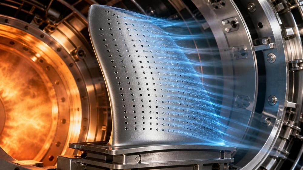
The basic idea of film cooling is straightforward: bleed a small amount of relatively cooler air through the blade surface and let it form a thin protective layer. The problem is that mainstream hot gas moves fast, the boundary layer is thin, and any disturbance can lift the coolant off the surface. A round hole drilled at the wrong angle may dump coolant into the flow instead of spreading it over the metal. An overly aggressive exit angle can help coverage on one part of the blade while creating local mixing loss or hot spots elsewhere.
Hole shape is one of the first choices engineers revisit. Cylindrical holes are simpler to make, but they do not always provide the best surface coverage. Shaped holes, including fan-shaped or laidback configurations, usually help the coolant spread laterally before it disperses. That wider coverage often improves film effectiveness, especially on leading-edge and pressure-side regions where the external flow is harsh. Still, a better coverage pattern does not automatically mean a better overall design. If the exit area is too large or the flow rate is poorly matched, the design may sacrifice too much compressor bleed air.
This is where evaluation teams need to look beyond a single performance number. Film cooling effectiveness is important, but so is the pressure loss created by extraction and discharge. A design that looks strong in thermal terms can still be unattractive if it increases engine-specific fuel consumption or disturbs the blade aerodynamics more than expected.
Angle, spacing, and density are not independent decisions
Hole angle affects how the coolant momentum compares with the mainstream flow. If the jet momentum is too high, the coolant tends to lift off. If it is too low, coverage may be stable but too narrow. Designers often adjust both compound angle and expansion angle to improve attachment across the surface. The goal is not simply to slow the jet down, but to guide it so the film can stay coherent across the blade profile.
Spacing matters just as much. Closely spaced holes can create good overlap, but they also increase manufacturing effort and may weaken the local structure if the blade wall is thin. Wider spacing reduces hole count and can simplify production, yet the film may break up between holes, especially where the external heat load is high. In real projects, this becomes a trade-off between thermal coverage, structural integrity, and process repeatability. That is why the same pattern may perform well on one blade platform and poorly on another with a different curvature, coating system, or internal cooling feed.
Cooling hole density also has a practical limit. More holes do not always mean better cooling. Once the local surface reaches a point where additional coolant merely increases mixing loss, further density gains become inefficient. At that stage, teams usually need to revisit the whole cooling architecture, not just add more perforations.
Manufacturing quality can erase a good design
Even a sound film cooling hole design can underperform if the holes are inconsistent. Small variations in diameter, edge quality, burr formation, or exit contour can change flow behavior more than many non-specialists expect. In high-temperature turbine service, that means one blade may cool acceptably while another in the same batch shows a weaker film attachment or an uneven temperature field. For this reason, design review cannot be separated from process capability review.
Manufacturing route matters as well. EDM, laser drilling, and other methods each introduce their own surface condition, heat-affected effects, and repeatability issues. A design that is practical on paper may be difficult to hold consistently at scale, especially when hole orientation is complex or when the blade uses advanced materials and coatings. For procurement and technical audit teams, this is not a minor detail. It affects yield, inspection load, rework risk, and ultimately lifecycle cost.
This is also where a B2B technical intelligence approach becomes useful. AATS, for example, sits at the intersection of aero-engine parts, materials, manufacturing capability, and reliability risk. Its role is not to sell a cooling solution, but to help buyers, suppliers, engineering consultancies, and MRO teams compare how a given design choice fits the rest of the system: superalloy behavior, coating compatibility, heat treatment route, and the inspection standard behind the part.
How to evaluate a proposed design without overclaiming
A practical review usually starts with a few questions. Does the hole geometry match the temperature map of the blade, or was it copied from another platform? Is the design intended to work with a specific coating system? What coolant mass flow is assumed, and what happens if operating conditions deviate from that assumption? These are not academic questions. In service, off-design operation is normal, and a design that only works well at one condition may be fragile in real engines.
The next step is to look at the trade-off between thermal benefit and aerodynamic penalty. If a design improves surface protection but requires a meaningful increase in cooling bleed, the engine may pay for that improvement elsewhere. For some applications, especially where life extension is the priority, that trade may still be acceptable. For other programs focused on efficiency and emissions, the threshold is stricter. There is no universal answer; the standard should be tied to mission profile, certification target, and maintenance strategy.
Teams also need to consider how the hole pattern behaves under deposit buildup, oxidation, or repair cycles. In MRO settings, a blade that has already seen thermal exposure may not respond the same way after refurbishment. That is one reason why film cooling assessment is often linked with dimensional inspection, coating condition review, and life consumption analysis rather than treated as a standalone feature.
Standard-driven thinking is better than design-by-instinct
Film cooling hole design is not something that should be judged only by visual intuition. Technical evaluation usually needs test data, CFD correlation, material limits, and the relevant acceptance criteria for the engine program. Depending on the application, that may involve internal company specifications, customer-defined requirements, or broader aerospace quality and process standards. The exact threshold for acceptability is project-specific, but the logic is consistent: a blade design must prove it can survive heat, preserve efficiency, and remain manufacturable with repeatable quality.
For suppliers, that means capability statements should go beyond “we can drill the holes.” Buyers increasingly want to know how the design was validated, what inspection method is used, how variation is controlled, and how the design behaves after repeated thermal cycling. For engineering teams, it means recognizing that cooling performance is not a single metric. It sits between aerodynamics, materials, manufacturing, and maintenance, and it should be reviewed that way.
In turbine blade programs, the best film cooling design is rarely the most aggressive one. It is usually the one that delivers stable protection, tolerable loss, and consistent production quality across the full life of the part. That is a narrower target, but a more realistic one. When teams assess film cooling hole design with that mindset, they make better decisions on blade durability, engine reliability, and long-term operating cost.
Related News
- What drives thermal barrier coating cost for turbine blade repairs?Sep 18, 2026Thermal barrier coating cost for turbine blade repairs depends on condition, repair scope, coatings, inspection, and turnaround. Learn how to compare quotes confidently.
- How to evaluate a thermal barrier coating supplier for turbine bladesSep 07, 2026Thermal barrier coating supplier evaluation guide for turbine blades—compare process control, approvals, testing, traceability, and lifecycle value with confidence.
- When do ultra high temp materials outperform nickel superalloys?Aug 31, 2026Ultra high temp materials outperform nickel superalloys when heat, cooling demand, weight, and lifecycle limits require smarter material choices. Explore key selection factors.
- What to check before choosing a single crystal turbine blade supplierAug 25, 2026Single crystal turbine blade supplier selection starts with process control, alloy capability, cooling feature accuracy, traceability, and lead-time risk. Learn what buyers should check before requesting quotes.