




Search
Related News
- 00
0000-00
How traction converter losses affect high-speed rail efficiency - 00
0000-00
How train crossing pressure waves in China affect nearby structures - 00
0000-00
How fatigue fracture analysis testing identifies crack initiation risks - 00
0000-00
How a CBTC fallback system keeps trains moving after link loss - 00
0000-00
When should a transit system engineering consultant join an EPC project?
How traction converter losses affect high-speed rail efficiency




At 350 km/h, a high-speed train is not simply “using electricity”; it is managing a tightly coupled energy chain. Power arrives from the overhead line, passes through the main transformer and traction converter, becomes controlled three-phase power for the motors, and finally turns into wheel torque. Each conversion step creates loss. On a short diagram, those losses may look modest. Across a fleet operating long daily distances, under hot ambient conditions and demanding timetables, they become a material part of energy cost, cooling-system load, equipment ageing, and service availability.
For technical evaluators, high-speed rail traction systems efficiency is therefore more than a converter efficiency figure taken at a single rated point. The useful question is: how much electrical energy is lost over the real duty cycle, and what secondary penalties do those losses create? The answer depends on semiconductor switching behavior, modulation strategy, transformer and filter design, cooling architecture, auxiliary consumption, harmonic performance, and the train’s operational profile.
Traction converter losses directly influence how efficiently high-speed trains turn grid power into reliable propulsion at operating speeds above 300 km/h. A sound assessment needs to consider switching losses, thermal management, cooling demand, harmonic performance, and component reliability together—not as isolated design chapters.
Where traction converter losses actually occur
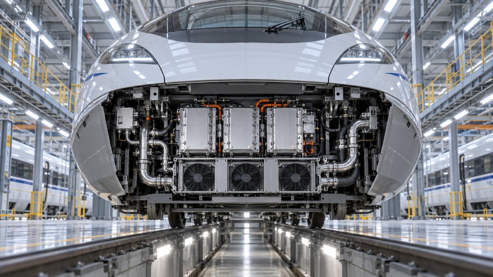
A modern high-speed traction chain typically includes a line-side converter or four-quadrant converter, a DC link, an inverter, traction motors, and associated filters, sensors, gate drives, and cooling equipment. In AC electrification systems, the transformer also sits upstream of the converter and deserves attention because its losses add heat before the conversion stage even begins.
The most visible losses occur in power semiconductor devices. Whether the equipment uses insulated-gate bipolar transistors (IGBTs), silicon carbide (SiC) MOSFETs, or another device family, there are two central categories:
- Conduction losses: generated while a device is carrying current. They are influenced by current level, device voltage drop or on-state resistance, junction temperature, and current waveform.
- Switching losses: generated when a device transitions between on and off states. These depend on switching frequency, DC-link voltage, current, gate-drive behavior, device characteristics, and commutation conditions.
At high propulsion demand, conduction loss can dominate because current is high for sustained periods. At lower torque or during operating modes that require higher switching frequency for acoustic, control, or harmonic reasons, switching loss may become more significant. The balance is not fixed. It shifts with speed, acceleration rate, line voltage variation, motor control strategy, temperature, and regenerative braking conditions.
There are also losses that receive less attention in headline converter specifications but matter in a whole-train energy model: capacitor ripple-current heating in the DC link, magnetic losses in inductors and filters, copper and core losses in transformers, busbar resistance, snubber and gate-drive consumption, control electronics, and coolant pumping. Fans, blowers, chillers, and heat exchangers may consume a relatively small amount individually, yet their combined annual energy use and maintenance burden can be substantial.
A converter’s heat output is not just an energy issue
Every kilowatt lost in a traction converter becomes heat that must be removed or tolerated. That changes the engineering problem. A train running through a cold climate may reject heat easily for much of the year, while a train operating in high ambient temperature, tunnels, dusty corridors, or congested depots faces a narrower thermal margin. The converter may still meet its nominal rating in a laboratory environment but encounter derating, more aggressive cooling operation, or accelerated component ageing in service.
Thermal cycling is often as important as peak temperature. Repeated acceleration, coasting, braking, station stops, and re-acceleration cause junction temperatures to rise and fall. Over time, that cycling can stress solder layers, bond wires, die attach interfaces, capacitors, and other assemblies. A design with slightly lower instantaneous loss but poor thermal distribution may not deliver the lifecycle outcome expected from its efficiency figure.
This is why a technical review should ask for loss maps and thermal maps, not only a single “maximum efficiency” value. A loss map shows behavior across voltage, current, speed, and switching-frequency operating points. A thermal map reveals whether heat is concentrated in a small number of modules, how evenly coolant is distributed, and where local hot spots may emerge.
Why high-speed operation changes the picture
High-speed rail energy demand rises sharply with velocity because aerodynamic resistance becomes increasingly dominant. The traction system must provide sustained power to overcome that resistance, particularly on open routes, gradients, and sections exposed to crosswind. Converter losses may represent only one part of the full energy balance, but they occur in a system already working near meaningful continuous power levels.
At these speeds, operational details matter. A train may spend long intervals in a narrow speed band near the line’s maximum permitted velocity. If the converter’s best efficiency point sits far from that band, annual losses can be noticeably higher than a nameplate calculation suggests. Conversely, a converter optimized only for top-speed cruising may perform less favorably on routes with frequent intermediate stops, long grades, or restrictive signaling patterns that demand repeated acceleration and braking.
Regenerative braking introduces another layer. During braking, traction motors act as generators and the converter returns energy to the overhead system or supports onboard loads. The conversion process still has losses, and recovered energy is only useful if the network can accept it, nearby trains can consume it, or an energy-storage strategy is available. Evaluators should avoid treating regenerative capability as a guaranteed energy credit. Its real value depends on timetable density, substation receptivity, voltage control, and route operation.
The switching-frequency trade-off
Increasing switching frequency can improve current waveform quality and make it easier to control motor torque smoothly. It may also reduce the size of some passive components. Yet each additional switching event adds energy loss in conventional semiconductor devices. Raising frequency without considering the full system can increase converter heat, cooling demand, electromagnetic interference risk, and stress on insulation systems.
Lower switching frequency can reduce switching loss, but it may increase harmonic content, acoustic noise, torque ripple, or the burden placed on filters and motor design. The practical objective is not “the highest frequency” or “the lowest loss” in isolation. It is a coordinated selection of semiconductor technology, modulation method, motor insulation capability, filter topology, EMC performance, and cooling capacity.
Wide-bandgap devices such as SiC can alter this trade-off because they generally support faster switching with lower switching loss than conventional silicon IGBTs under appropriate conditions. However, a technology change is not automatically a system-level efficiency win. Faster voltage transitions can increase common-mode effects, bearing-current concerns, EMI challenges, and requirements for layout discipline, shielding, filtering, and insulation coordination. Procurement teams should look beyond the device data sheet and assess the maturity of the converter architecture around it.
Cooling power can erase part of the gain
It is tempting to report traction converter efficiency independently from the cooling system. For vehicle-level evaluation, that separation can be misleading. If a converter dissipates more heat, pumps and fans run harder, radiators need more capacity, and air paths may become more sensitive to fouling. If liquid cooling is used, the design must manage pump power, coolant quality, leakage risk, corrosion control, and service access.
There is a useful distinction between electrical conversion efficiency and net traction-system efficiency. The former measures power-device and converter losses. The latter should include the auxiliary energy required to keep the converter within its allowable temperature range. A design that improves semiconductor efficiency but requires a disproportionately complex cooling package may still be justified for reliability or packaging reasons, but that case should be made transparently.
Environmental loading should be included in qualification planning. Heat exchangers gradually lose performance when exposed to dust, insects, salt, ballast debris, and maintenance variability. A thermal design that has little margin when clean may become problematic before its next scheduled service interval. This is particularly relevant for fleets that combine high-speed intercity duty with demanding regional operating conditions.
Harmonics, power quality, and losses outside the vehicle
Traction converters influence efficiency beyond the train itself. On the line side, poor harmonic behavior or unfavorable power-factor performance can increase losses in transformers, cables, substations, and catenary equipment. Modern four-quadrant converters are designed to control input current and support regenerative operation, but actual performance must be verified across realistic supply voltages and network impedance conditions.
A vehicle can meet a formal harmonic requirement yet still create operational challenges on a particular network if multiple trains interact with resonance points in the electrification system. The resulting voltage distortion can affect converter control stability, protective settings, and the usable capacity of the traction power supply. From an infrastructure perspective, efficient traction conversion is therefore partly a network-compatibility issue.
Technical evaluators should request evidence aligned with applicable regional railway standards and project specifications, including EMC, insulation coordination, temperature, vibration, fire safety, and functional safety requirements where relevant. The exact standard set varies by market and vehicle platform. What matters is that claimed efficiency is demonstrated without shifting risk into power quality, maintenance effort, or interoperability.
How to assess high-speed rail traction systems efficiency in a tender
Comparing two propulsion packages using one percentage value is a common but avoidable mistake. A stronger evaluation framework starts with the expected route duty cycle: station spacing, gradients, maximum speed, dwell time, ambient range, altitude, passenger load, electrification voltage, and regenerative receptivity. Suppliers can then provide modeled energy consumption and loss breakdowns for the same reference mission.
Questions worth putting into a technical clarification schedule include:
- At which DC-link voltage, output power, switching frequency, and coolant temperature was the stated converter efficiency measured?
- Can the supplier provide efficiency and loss curves across traction, cruise, auxiliary, and regenerative braking modes?
- What proportion of loss arises in semiconductors, magnetics, DC-link components, and cooling auxiliaries?
- How does the system behave at high ambient temperature, reduced cooling performance, low line voltage, and degraded fan or pump conditions?
- What junction-temperature cycling assumptions support the predicted power-module lifetime?
- How are capacitor health, coolant flow, fan speed, insulation condition, and thermal margin monitored?
- What maintenance actions are required to preserve cooling and conversion performance over the vehicle lifecycle?
This approach makes efficiency measurable in operational terms. It also exposes differences between a design optimized for an ideal test point and one built for stable, repeatable performance over years of railway service.
Reliability and maintainability belong in the energy calculation
A converter that saves energy but causes more depot intervention may not be the better asset. High-speed fleets are highly utilized, and an unavailable trainset can disrupt diagrams, maintenance planning, and passenger confidence. Component accessibility, modular replacement time, diagnostic coverage, spare-parts strategy, and condition-monitoring quality all influence lifecycle value.
Predictive maintenance can support efficiency as well as availability. Rising thermal resistance, abnormal coolant temperature differentials, unexpected fan power, DC-link capacitor temperature, and drift in switching behavior can indicate degradation before a fault occurs. Monitoring these parameters allows maintainers to correct a cooling or power-electronics issue while the train is still within a controlled maintenance window rather than after a service failure.
There is also a human factor. Engineering teams need diagnostic information that is interpretable, not merely abundant. A useful maintenance system connects alarms to likely causes and gives technicians enough context to distinguish a temporary operational event from a developing hardware problem.
What good optimization looks like
The most credible traction efficiency strategy is balanced. It combines low-loss power devices with an appropriate switching strategy, robust DC-link and magnetic design, effective thermal paths, manageable cooling auxiliaries, compliant harmonic performance, and condition monitoring that protects long-term reliability. It is not a race for an isolated laboratory number.
For high-speed rail programs, the key decision is to evaluate losses as part of the full propulsion and infrastructure ecosystem. A few watts saved in a module matter only when they reduce real energy use, avoid unnecessary cooling work, preserve thermal margin, and remain achievable after years of vibration, weather exposure, and repeated service cycles. That is the practical meaning of high-speed rail traction systems efficiency: converting as much available electrical energy as possible into dependable movement, while keeping the heat, network impact, and lifecycle risk under control.
Related News
- How traction converter losses affect high-speed rail efficiencySep 25, 2026High-speed rail traction systems efficiency: discover how converter losses affect energy use, cooling demand, reliability, and lifecycle costs at 300+ km/h.
- When does condition based predictive maintenance pay off for traction convertersAug 20, 2026Condition based predictive maintenance pays off for traction converters when it improves intervention timing, parts planning, and fleet priorities—cutting failures, waste, and disruption.
- EMU Traction Converters Explained: Key Performance Metrics That Matter in Specification ReviewsJul 10, 2026EMU traction converters explained clearly: discover the key performance metrics that shape efficiency, thermal stability, reliability, and smarter procurement decisions.
- EMU Traction System Engineering: Key Risks in Converter IntegrationJul 07, 2026EMU traction system engineering insights on converter integration risks, covering interfaces, thermal loads, software coordination, and EMC control to improve delivery success.