




Search
Related News
- 00
0000-00
When does condition based predictive maintenance pay off for traction converters - 00
0000-00
What aerospace materials engineering certification should verify for fastener traceability - 00
0000-00
How propulsion system aerodynamics affects fuel burn at cruise - 00
0000-00
How derailment prevention systems are evaluated for high-speed rail safety - 00
0000-00
When does bridge structural health monitoring justify the cost
Aero-Engine Thermal Management Challenges and Practical Solutions




Why aero-engine thermal management must be judged by operating context
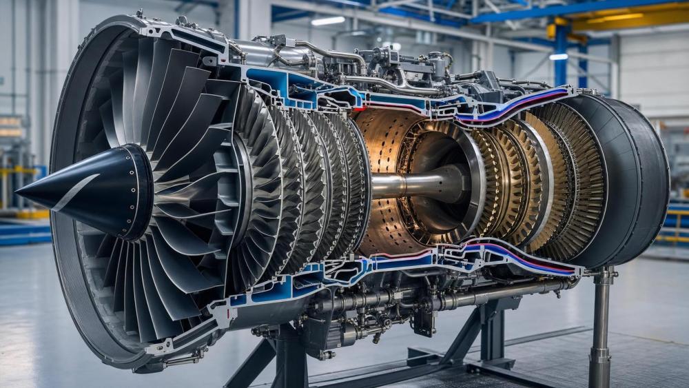
Aero-engine thermal management sits at the center of reliability, fuel burn, durability, and inspection planning.
The issue is not heat alone. It is how heat moves through blades, vanes, casings, seals, combustors, and rotating structures under changing loads.
In practical use, the same engine architecture can face very different thermal stress patterns.
A long cruise profile, repeated hot starts, dusty takeoff environments, and aggressive power transients do not challenge components in the same way.
That is why aero-engine thermal management cannot be reduced to a single temperature limit or cooling figure.
More useful evaluation looks at thermal gradients, dwell time, local oxidation, creep exposure, cooling effectiveness, and maintainability across the engine life cycle.
Within AATS-style industrial analysis, this matters because thermal performance links materials, manufacturing quality, certification readiness, MRO planning, and supplier capability.
A component that performs well in lab data may still fail early if the operating scenario creates unstable heat distribution or blocked cooling passages.
Different flight profiles create different thermal management priorities
One common mistake is treating all thermal loads as peak-temperature problems.
In reality, aero-engine thermal management often becomes a tradeoff between maximum temperature and time at temperature.
For engines with long steady cruise periods, the main concern often shifts toward creep accumulation in turbine blades and vanes.
Single-crystal superalloys, thermal barrier coatings, and stable film cooling patterns become especially important there.
A different pattern appears in duty cycles with frequent takeoff, climb, throttle variation, and shutdown.
Those engines may see stronger thermal fatigue because repeated expansion and contraction drive cracking around cooling holes, seals, and attachment zones.
The judgment point changes again in hot-and-high conditions.
Available cooling air becomes more limited, while combustor exit temperatures stay demanding.
In that setting, aero-engine thermal management depends heavily on internal passage design, pressure ratio, and leakage control, not just material rating.
Where the thermal risk usually concentrates
- First-stage turbine blades facing the highest gas temperature and centrifugal load.
- Combustor liners where local hot streaks can accelerate oxidation and distortion.
- Engine casings and shrouds where clearance control affects both efficiency and rub risk.
- Cooling passages vulnerable to deposits, roughness change, or manufacturing deviation.
When material capability matters more than nominal cooling performance
Aero-engine thermal management is often discussed through cooling technology, but materials decide how much thermal margin can actually be used.
This is especially true where high gas temperature meets long service exposure.
Single-crystal superalloys help resist creep, yet their value depends on casting quality, grain control, coating adhesion, and heat treatment consistency.
If those process conditions drift, thermal resistance becomes less predictable even before visible damage appears.
Film cooling systems also look strong on paper, but practical effectiveness changes with hole geometry, surface condition, and mainstream flow behavior.
A minor manufacturing variation can disturb coolant attachment and raise local metal temperature sharply.
That is why aero-engine thermal management should be assessed together with process capability and inspection evidence.
In sectors where certification and export readiness matter, traceable metallurgy and controlled thermal processing are part of the thermal solution, not background paperwork.
The same thermal challenge looks different in new production and in-service maintenance
New engine production usually focuses on design margin, repeatable manufacturing, and validation testing.
In service, the concern becomes thermal drift over time.
Cooling holes may collect contaminants. Coatings may thin. Tip clearances may shift. Small distortions can change local heat flow.
At that stage, aero-engine thermal management is no longer only a design discipline. It becomes a condition-monitoring discipline.
A practical maintenance view looks for trends rather than isolated values.
Exhaust gas temperature margin, borescope findings, coating spallation, distortion around combustor hardware, and recurring hot-section repairs should be read together.
This is where AATS-style cross-domain reporting adds value.
Thermal management decisions often sit between materials data, MRO practice, inspection technology, and lifecycle economics rather than in one isolated engineering report.
A quick comparison of thermal priorities by scenario
Practical solutions work best when matched to the failure mechanism
There is no single fix for aero-engine thermal management because overheating does not arise from one cause.
If the problem is local hot streaking, combustor pattern control and flow uniformity deserve attention.
If the issue is blade metal temperature, internal cooling design and film coverage may offer better returns.
Where casing distortion affects clearances, thermal control may need to involve shroud materials, seal design, and transient warm-up behavior.
Several practical solutions appear repeatedly across modern programs:
- Refined film cooling hole layouts to improve coolant coverage with less bleed penalty.
- Advanced thermal barrier coatings with stronger adhesion and oxidation resistance.
- Single-crystal and directionally solidified materials for hot-section durability.
- Better combustor temperature pattern control to reduce downstream hot spots.
- Predictive inspection based on temperature trend data and hot-section condition history.
The best solution usually balances thermal protection with fuel efficiency, manufacturing complexity, and repairability.
An aggressive cooling scheme that reduces efficiency or becomes difficult to inspect may not be the right answer in real service.
What is often misjudged before implementation
A recurring misjudgment is assuming similar engines face identical thermal conditions.
Differences in mission profile, ambient environment, start frequency, and maintenance discipline can change the thermal picture considerably.
Another weak point is focusing on design temperature while ignoring thermal gradients.
Sharp local gradients often trigger cracking and coating loss earlier than average temperature data would suggest.
Cost is also misread when only acquisition price is compared.
In aero-engine thermal management, lifecycle cost depends on inspection burden, repair frequency, coating recovery, and unplanned removal risk.
The more practical judgment method is to connect thermal design choices with service intervals, process control, and downstream MRO feasibility.
Checks worth making before choosing a thermal approach
- Confirm whether the main risk is creep, oxidation, fatigue, distortion, or deposit-driven blockage.
- Review real duty cycles instead of relying only on rated operating points.
- Check whether manufacturing tolerances can hold the intended cooling geometry.
- Verify inspection access and repair methods for coated or internally cooled parts.
- Compare fuel, durability, and maintenance tradeoffs together rather than one by one.
A practical next step for stronger aero-engine thermal management decisions
Better aero-engine thermal management starts with a sharper scenario map.
List the real operating profile, thermal exposure duration, environmental conditions, material system, cooling architecture, and inspection constraints.
Then compare those conditions against failure history, coating performance, passage cleanliness, and repair intervals.
This approach helps separate problems caused by design margin from those caused by production variation or service deterioration.
For technical and commercial evaluation, it is also worth aligning thermal data with certification evidence, process capability, and lifecycle maintenance assumptions.
That is usually where a more reliable decision emerges: not from one temperature number, but from a full view of application fit, risk, and long-term support.
Related News
- China Tightens Export Rules for Titanium Engine CasingsAug 13, 2026China tightens export rules for titanium engine casings with Nadcap heat-treatment review and SIL4 documentation. Learn how the new policy impacts audits, compliance, and shipment timing.
- FAA Tightens Heat-Treatment Rules for Aerospace ForgingsAug 12, 2026FAA tightens heat-treatment rules for aerospace forgings under AC 21.303-2D, raising traceability and Nadcap HT demands. See what suppliers, MROs, and exporters must do now.
- FAA Tightens Nadcap Heat Treatment Rule for Titanium CasingsAug 08, 2026FAA Tightens Nadcap Heat Treatment Rule for Titanium Casings: learn how the 2026 FAA update impacts U.S. export compliance, OEM sourcing, traceability, and delivery readiness.
- How to Evaluate an Engine Casing Supplier for Material Traceability and Nadcap ComplianceAug 04, 2026Engine casing supplier evaluation starts with traceability and Nadcap scope, not shop claims. Learn how to verify records, special processes, and audit red flags before approval.